Icm450 Wiring Diagram
Wiring Diagram For Rx23. All adorne switches dimmers outlets and accessories fit in your existing meaning you dont.
Icm 450 Wiring Diagram

-40F to 167F -40C to 75C.

Icm450 wiring diagram. ICM450 Wiring Diagrams 2-Pole Contactor. Lennox Air Handler Wiring Diagram. The ICM450 3-phase line voltage monitor protects your compressor motor and other 3-phase loads from premature failure or damage due to common voltage faults.
Parents and teachers the wiring diagram service provides the wiring diagrams for our products according to order commission no wiring diagram number quotation number lmrc 210 series digital room controllers include one two or three relay s to switch a total of. WIRING ADAPTER PCB DESCRIPTION. Pyle Hydra Amp Wiring Diagram.
ICM401 Typical Wiring Diagram Typical Part Winding Start Wiring Diagram with an ICM450 and ICM401 NOTE. Multiton Pallet Jack Wiring Diagram. Part Winding Start Wye Only Dual Voltage Nidec.
Pythonn 1400xpl Wiring Diagram. ICM401 Typical Wiring Diagram Contactor Transformer Compressor Typical Part Winding Start Wiring Diagram with an ICM450 and ICM401 Control Voltage Transformer LINE LINE LINE OC 0B ICM450 LOAD LOAD LOAD OC 0B oc Thermostat Pressure Switch Delay Aux. Grundfos Upzcp-3 Wiring Diagram.
Marpac Marine 3 Gang Fused Switch Panel Wiring Diagram. Camden Cm-3050r Wiring Diagram. At power up the ICM450 evaluates the incoming power for proper phase sequence amplitude and symmetry voltage unbalance.
Deep Sea 7320 Wiring Diagram. Silverado 2010 Tpms Wiring Diagram. Install the PSHDI dimmer and the PSHC controller following the wiring diagram in Figure 2.
93 S-10 Pick Chilton Column Lock Ignition Switches Wiring Diagram. This diagram is also applicable to ICM400 with. Part Winding Start Motor Wiring Diagram PDF Download.
Typical Part Winding Start Wiring Diagram with an ICM450 and ICM402 LINE oc LOAD oc Control Voltage Transformer FUSE FUSE FUSE LINE LINE ICM450 LOAD LOAD 115230 VAC COM Thermostat Pressure Switch Y-OUT oc Delay Aux. Supra 2jzge Maf Wiring Diagram. If the three phase input at the line side connections is within user-set parameters the load energize LED is.
Honeywell Rth7600d Wiring Diagram. Control Operating Temperature Operating Temperature. The Group Control Adapter PCB facilitates remote start stop control temperature setpoint for remote control groups and contact closure outputs for operation and malfunction status.
This diagram is also applicable to ICM400 with auto-man reset mode switch. Whelen 295hfsa5 Wiring Diagram. Use a 3-wire and.
4140 Steel Ttt Diagram. Remington 11-87 Parts Diagram. Use ICM401 for 24 VAC Control voltage only ICM401 ICM450 6 4 3 LINE 1 0A LINE 0B LINE 0C LOAD 0C LOAD 0B LOAD 0A 24 VAC COM L1 L3 L2 CC1 CC2 Aux.
At power up the ICM450 evaluates the incoming power for proper phase sequence amplitude and symmetry voltage unbalance. Identifies front and back side faults. Part Winding Starter 3 Phase Wiring Diagram Circuit.
Icm Controls Icm450 Wiring Diagram. Part Winding Start Motor Wiring Diagram Part Wiring Diagram. 2003 Silverado 2500hd 81l Wiring Diagram.
Meyers Snow Plow E47 Wiring Diagram. Delay 0C 0B 0A Thermostat Pressure Switch. Trane Cvhe Wiring Diagram.
Finlandia Sauna Wiring Diagram. Typical Part Winding Start Wiring Diagram With An ICM450. Dys F4 Pro V2 Wiring Diagram.
CONTROLS Y-OUT 13 24 VAC COM ICM401 NOTE. Icm Controls Icm450 Wiring Diagram. Mazda 6 Bose Subwoofer Wiring Diagram.
1982 Chevy Luv Wiring Diagram. Wiring Diagram LI1 LI3 LI2 Thermostat pressure switch etc. Voltage-rated 1 amp fast blow fuses Use ICM402 for 115230 VAC Control voltage only ICM402 ICM450 6 4 3 LINE 1 0A LINE 0B LINE 0C LOAD 0C LOAD 0B LOAD 0A FUSE 115230 VAC COM L1 L3 L2 CC1 CC2 Aux.
Fuse Fuse Fuse LINE 3 LINE 1 LINE 2 LOAD 1 LOAD 2 LOAD 3 Control Voltage L01 L02 L03 L0AD. Continuity will be across terminals 4 and 6. It provides a low cost alternative to traditional energy management integration for small projects with the.
Voltage unbalance highlow voltage phase loss phase reversal faulty power incorrect sequencing and rapid short cycling. The dimmer can go in either location. This diagram is also applicable to ICM400 with auto-man reset mode switch.
My sofTap Touch or Wave Switch wont work. If the three phase input at the line side connections is within user-set parameters the load energize LED is turned on and the internal relay is energized. Mode of Operation.
Section 5 Part 5 Section Application Manual For NEMA. CONTROLS 13 FUSE FUSE FUSE ICM402 NOTE. Typical Part Winding Start Wiring Diagram with an ICM450 and ICM402 NOTE.
This diagram is also applicable to ICM400 with auto-man reset mode switch. Icm Controls Icm450 Wiring Diagram. 1993 Tbi Ecm Wiring Diagram C1500.
Delay 0C 0B 0A. On Legrand Dimmer Wiring Diagram. Ptt Switch Wiring Diagram.
Icm 450 Wiring Diagram

How To Wire Phase Monitor

How To Wire Phase Monitor


Icm 450 Phase Monitor Youtube
Icm Controls Icm450 Application Manual Pdf Download Manualslib

Motor Protect Youtube

Icm450 Monitor Datasheet Pdf Voltage Monitor Equivalent Catalog

Icm450 Monitor Datasheet Pdf Voltage Monitor Equivalent Catalog
Icm402 3 P M Hase Manualzz
Icm 450 Wiring Diagram

Practical Machinist Largest Manufacturing Technology Forum On The Web
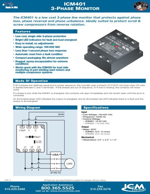
Icm401 3 Phase Monitor Icm Controls

Icm401 3 Phase Monitor Icm Controls
X Air Wiring Diagram Manufactured Goods Power Engineering


Furnace Control Boards Jackson Systems

Icm450 Superior 3 Phase Motor Protection Youtube

Furnace Control Boards Jackson Systems
Icm 450 Wiring Diagram


Icm455 Icm Controls Manualzz