System Sensor 2351e Smoke Detector Wiring Diagram
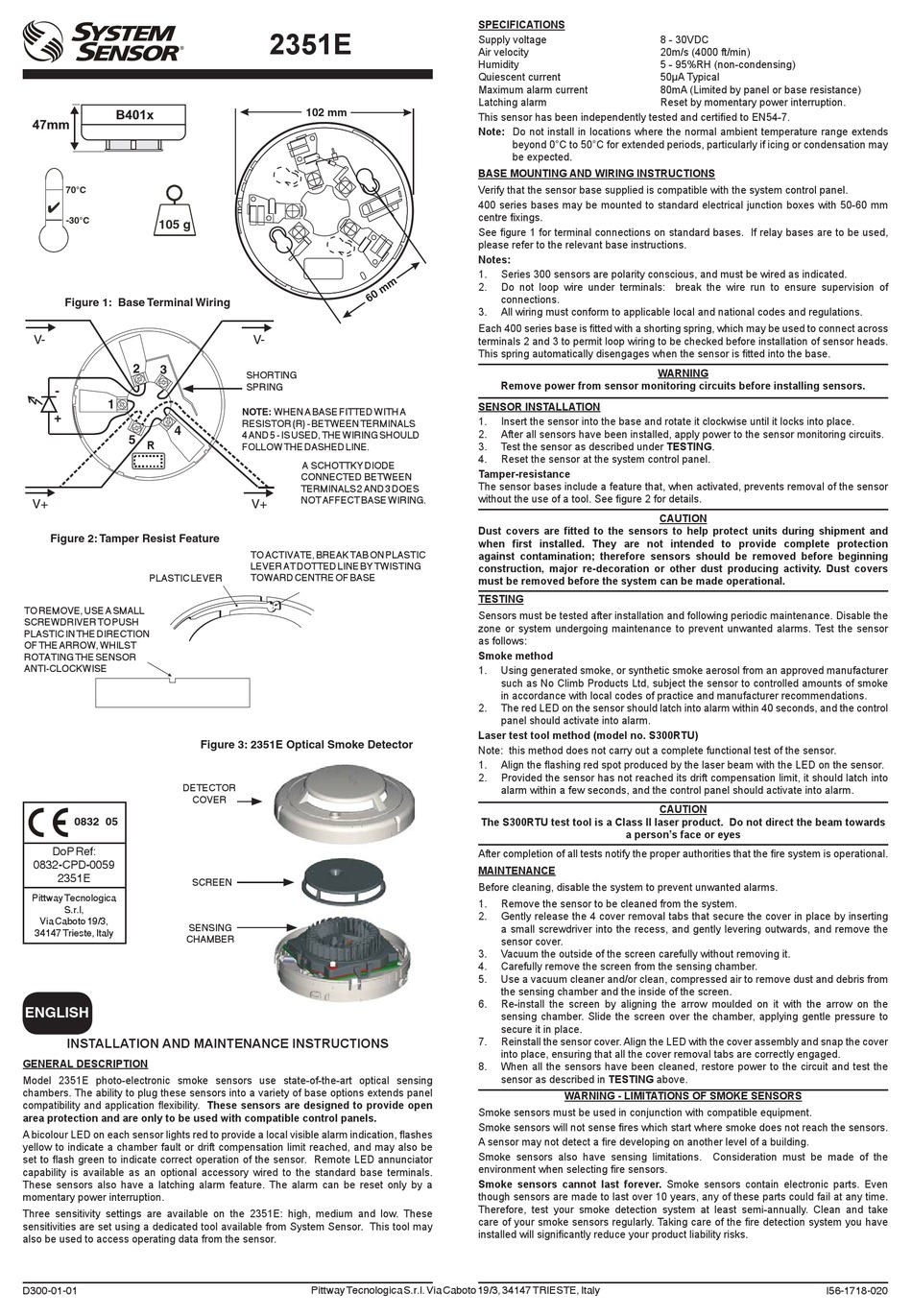
System sensor 2351e smoke detector wiring diagram system sensor conventional smoke detector wiring diagram system sensor smoke detector connection diagram. System Sensor 2351E Optical Smoke Detector Features.
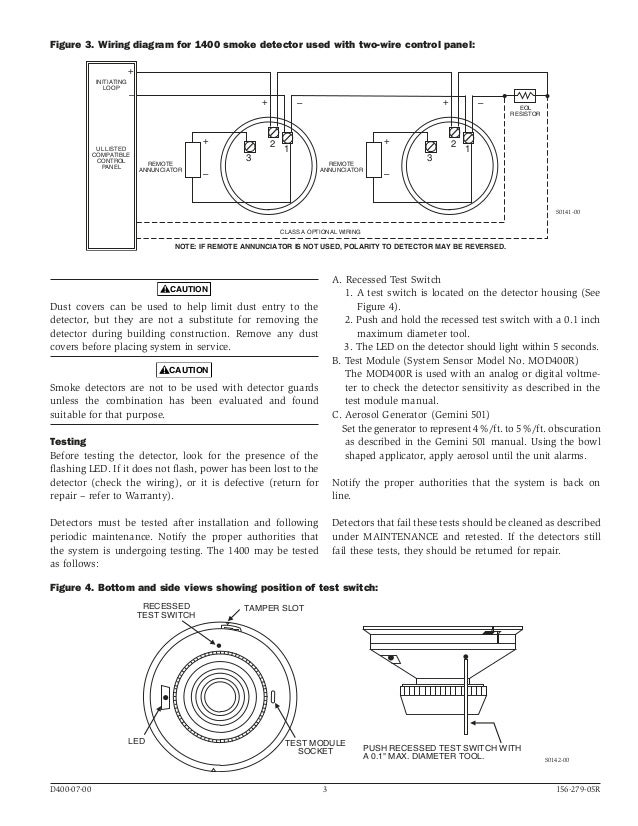
System Sensor 1400 Manual I56 0279
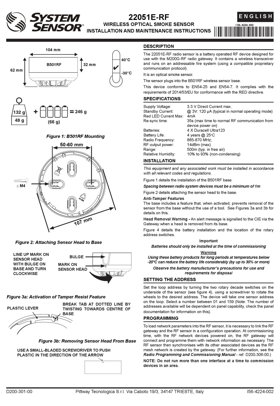
After all detectors have been installed apply power to the alarm control unit.
System sensor 2351e smoke detector wiring diagram. The 2351e photoelectric smoke detector forms part of the series 300 range of conventional detectors. Connect the wires to the detector per Figure 3 or Figure 4 as applicable. This image Vista 20P Smoke Detector Installation pertaining to System Sensor Smoke Detector Wiring Diagram above can be branded with.
System sensor smoke detector wiring diagram collection system sensor d4120 wiring diagram. The 2351E detector incorporates a bi-colour LED indicator. In our basic wiring diagram a single or multiple heat and smoke detectors are installed in the home by connecting the live line or hot neutral ground and an interconnected wire to the alarm.
Even though sensors are made to last over 10 years any of these parts could fail at any time. Mit einem speziellen System Sensor Werkzeug knnen diese Einstellungen durchgefhrt und auch auf die Betriebsdaten des Brandmelders zugegriffen werden. Placed by simply Tops Stars Team on November 18 2017.
This is available online from System Sensors web site. The System Sensor 2351E photoelectric detector incorporates an Application Specific Integrated Circuit ASIC. Conventional optical smoke detector.
Place the detector onto the mounting bracket by rotat- ing clockwise. This chart contains the current list of detectors and UL Listed compatible control units. It reveals the elements of the circuit as simplified shapes as well as the power and signal connections between the gadgets.
Therefore test your smoke detection system at least. Smoke sensors contain electronic parts. The 2351E photoelectric detector incorporates an Application Specific Integrated Circuit ASIC.
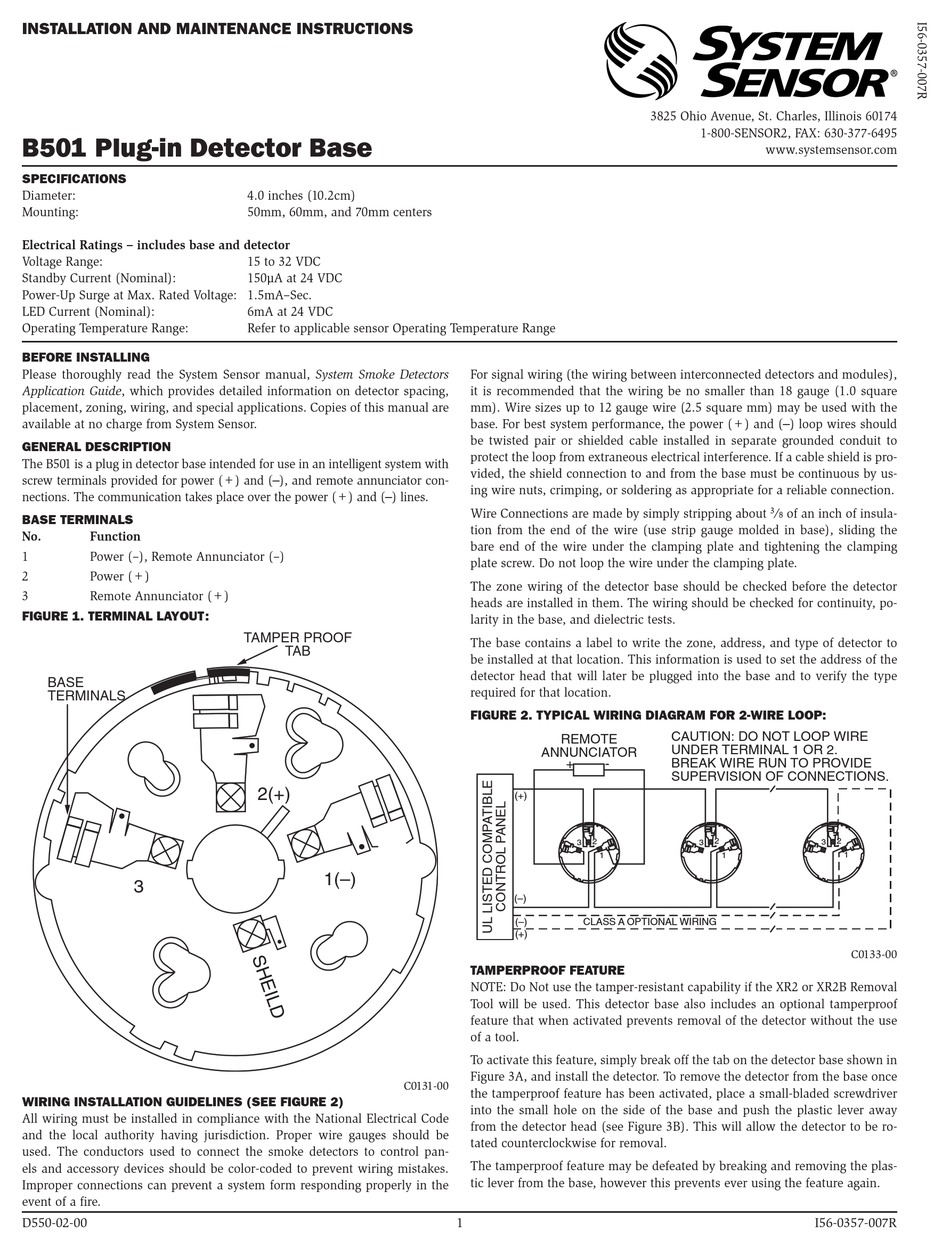
This manual shall be left with the owneruser of this equipment. This manual shall be left with the owneruser of this equip-ment. The 2351E and other detectors in the Series 300 range are backward compatible with the Series 100 detector bases thus providing the capability to upgrade extend and maintain existing Series 100 installations.
WIRING DIAGRAM 2W-B AND 2WT-B 2-WIRE ZONE 2-WIRE CONTROL PANEL 2W-B or 2WT-B 5 RA 4 RA 3 INOU T 2 OU T 1. A smoke or heat detector can be installed to the existing or new home wiring. So we attempted to uncover some good system sensor smoke detector wiring diagram.
Consideration must be made of the environment when selecting fire sensors. Combined with the latest state of the art optical chamber the detector provides efficient and accurate detection of fires with a high level of resilience to non-fire environmental influences. As identified by System Sensors compatibility chart.
The detector will lock into place with a click. Copies are available on System Sensors web site. The feature is only available on the d4120 4 wire conventional models.
A copy of this list is available from System Sensor upon request. Smoke sensors cannot last forever. Smoke sensors also have sensing limitations.
System Smoke Detectors which provides detailed information on detector spacing placement zoning wiring and special applications. The integral LED changes colour according to the detectors status - Green Normal Red Alarm. Free vehicle wiring search.
System Sensor 2351e Smoke Detector Wiring Diagram Light Lst 2351e User Manual Manualzz System Sensor 2100at Installation And Maintenance Instructions Pdf Manualslib. Please read thoroughly System Sensors Applications Guide for System Smoke Detectors SPAG91 which provides detailed information on detector spacing placement zoning wiring and special applications. Please read thoroughly System Sensor Application Guide.
The 2351E detector incorporates a bi-colour LED indicator. Home alarm wiring for a new house. Wiring diagrams for smoke detector diagram pdf duct wiring within.
Honestly we also have been noticed that system sensor smoke detector wiring diagram is being just about the most popular subject right now. In our basic wiring diagram a single or multiple heat and smoke detectors are installed in the home by connecting the live line or hot neutral ground and an interconnected wire to the alarm. Please Applications Guide for System read thoroughly System Sensor Smoke Detectors which provides detailed information on detector spacing placement zoning wiring and special applications.
Conventional optical smoke detector automatic drift compensation voltage 8-30VDC current 016mA quiescent and 80mA in alarm IP43 when installed on WB-1 shroud -30 to 70C certificate 0832-CPD-0059 Ademco 2610EC. This is the basic fire alarm system used in household wiring. Conventional Spot-Type Smoke Detector Bases System Sensor pertaining to System Sensor Smoke Detector Wiring Diagram image size 500 X 500 px and to view image details please click the image.
The 2351E and other detectors in the Series 300 range. WIRING DIAGRAMS FIGURE 3A. INSTALLATION AND MAINTENANCE INSTRUCTIONS FOR MODEL 2351E LOW PROFILE PHOTOELECTRONIC SMOKE DETECTOR Before installing detectors please thoroughly read System Sensors guide for the proper use of system smoke detectors which p rovides detailed information on detector spacing placement zoning wiring and special applications.
Break wire runs to provide system supervision of connections. Variety of duct smoke detector wiring diagram. Copies are available on System Sensors web site.
Simplex fire alarm wiring diagrams schematics and addressable smoke. Wiring for 4 wire duct smoke detector and accessories important notes on 21 sensor. This benefits the user by providing clear instant visual indication of the detectors condition.
The integral LED changes colour according to the.

Conventional White Smoke Detector System Sensor For Office Buildings Id 20980630530

System Sensor Smoke Detector 2351e Amazon In Electronics
System Sensor 5351e Manual Pdf Download Manualslib

System Sensor Smoke Detector 2351e Amazon In Electronics
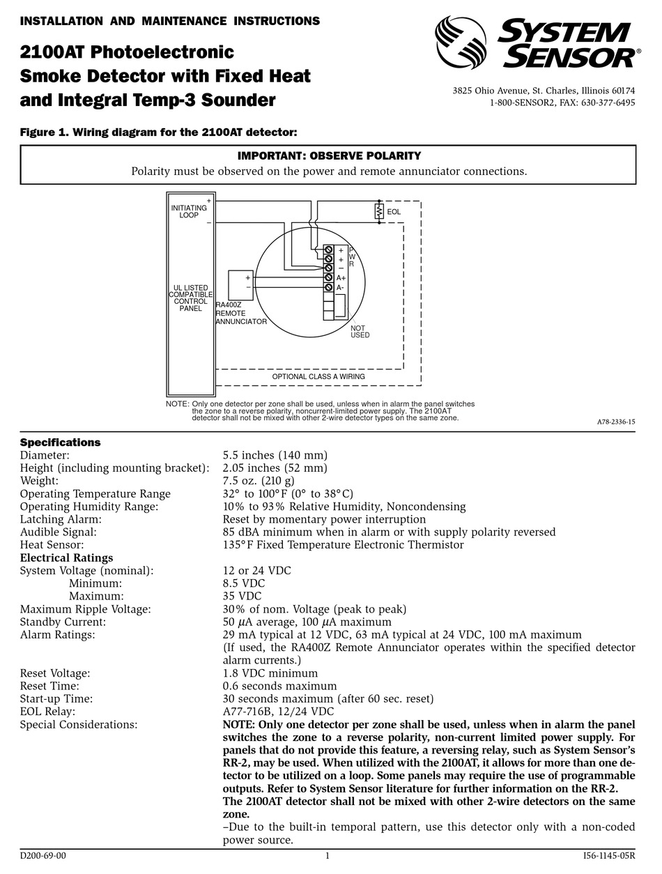
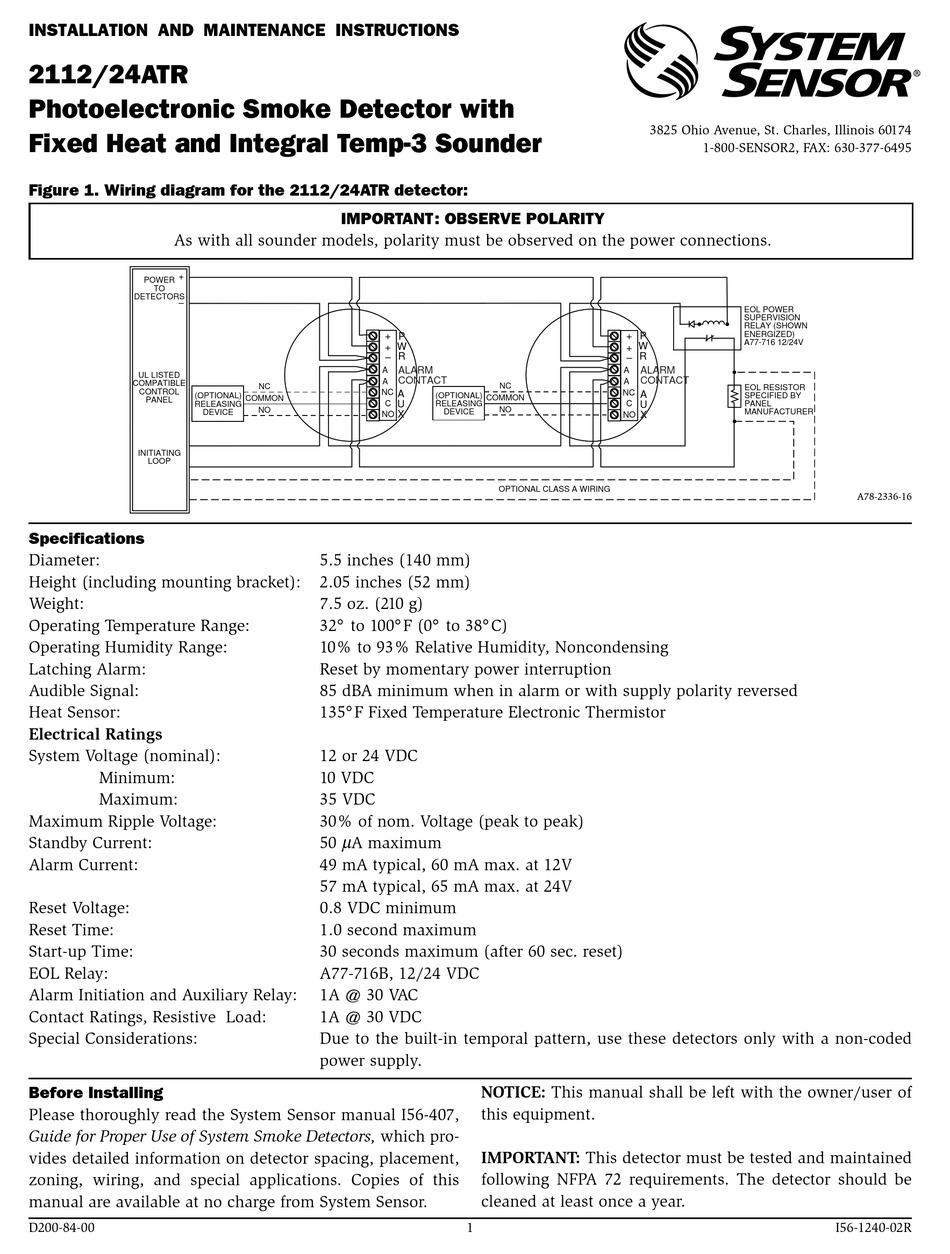
System Sensor 2100at Installation And Maintenance Instructions Pdf Download Manualslib
Re316 Installation Manual Relay Electrical Wiring


I56 1718 011 2351e A Manual Cpd Pmd System Sensor Canada

Plastic Honeywell Smoke Detectors Model Number 2351e Id 20932727991

Installation And Maintenance Instructions For Model 2351e Low Manualzz

Hardwired Smoke Detectors System Sensor Alarm Wiring Smoke Detector Wiring Diagram Fire Alarm
System Sensor 22051e Rf Installation And Maintenance Instructions Manual Pdf Download Manualslib

Installation And Maintenance Instructions For Model 2351e Low Profile Photoelectronic Smoke Detector Manualzz
System Sensor 2351e Installation And Maintenance Instructions Pdf Download Manualslib

System Sensor 2351tem Installation And Maintenance Instructions Pdf Download Manualslib
System Sensor 2112zh 24atr Installation And Maintenance Instructions Pdf Download Manualslib

Warm Grey 1c Photoelectric Conventional 2351 Ec System Sensor For Office Buildings Id 21282778597

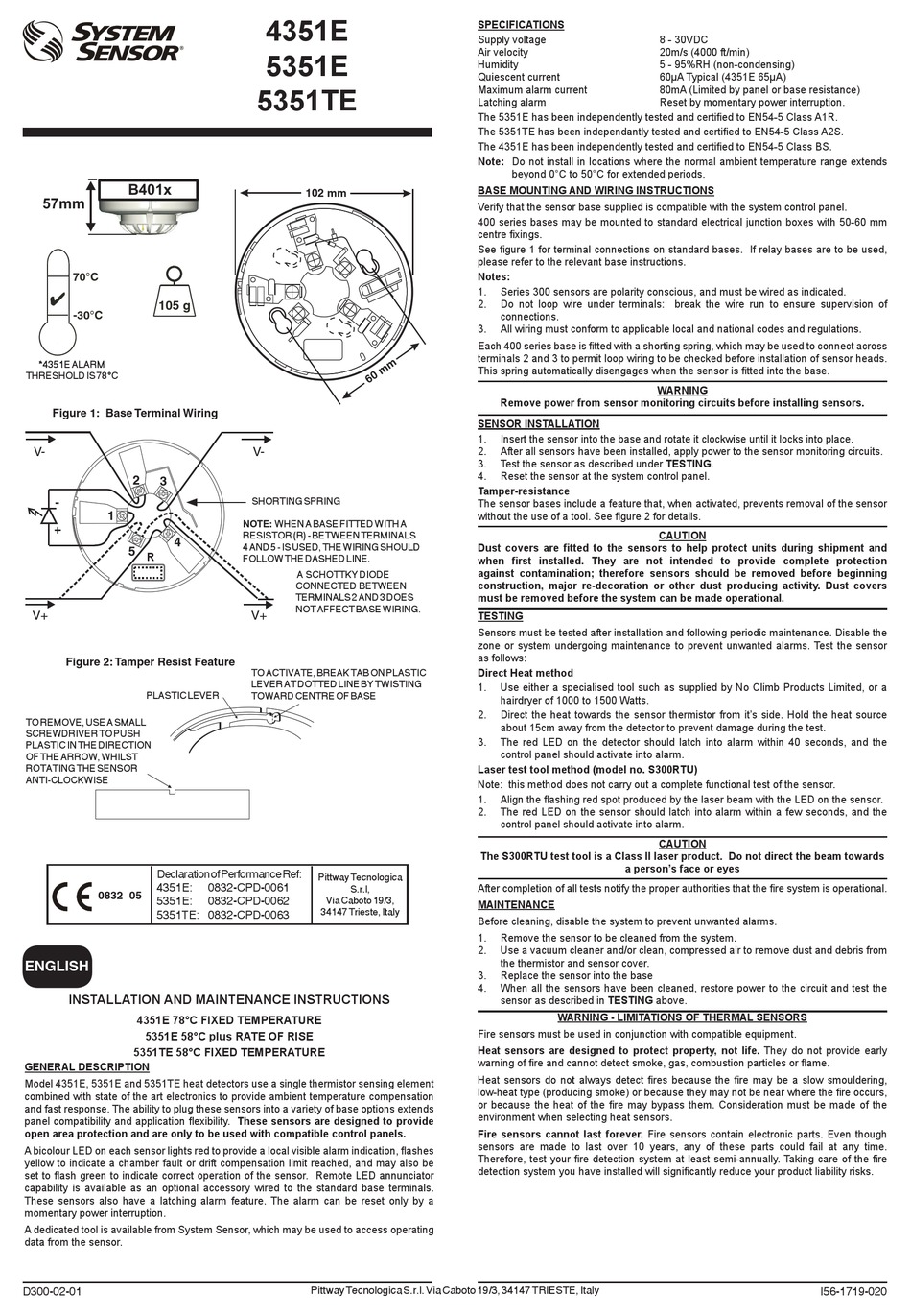
5451eis System Sensor Europe Manualzz
System Sensor B501 Installation And Maintenance Instructions Pdf Download Manualslib