Trol A Temp Wiring Diagram
EWC MAN WIRING A DAMPER TO A 3 WIRE THERMOSTAT AND as shown in diagram on left. Wiring is the same for AOBD AOBD-BM and IOBD Dampers.

Hyundai Atos Wiring Diagram Wiring Diagrams Wni
Ez 0717 By Honeywell Trol A Temp Wiring Diagram Schematic.
Trol a temp wiring diagram. As you have posted it looks like zone 2 and zone 3 stats are wired incorrectly you have blue and white crossed w blue r white and y red. If the fan shuts off its on the low volt side. Behind the blower door.
And move them to the corresponding terminals on the equipment terminal strip on the TrueZONE. The first step to properly wiring your new thermostat is to carefully label the existing wires labels included in your Ritetemp thermostat package on the wires. The fan contacts could be stuck closed.
My understanding is with the separate O and B wires the Nest is not compatible. Honeywell trol a temp wiring diagram schematron org honeywell trol a temp manual wsntech net wiring diagrams wiring diagrams 68 0229 tvc timed ventilation control zone panel professional installation guide connection. Heat to Cool switch function on the main thermostat is manual.
Diagram By Honeywell Trol A Temp Wiring Full Version Hd Quality 102231 Bundestagger De. Ues to run when all zones are satisfied reverse the. When using the ARD-PO wire to the.
Identify the conductors that are landed on the old panel Y G R. EWC Controls NCM NCM 23 ZONE CONTROL PANEL. Use only thermostats listed in Table 1.
I need a C Common wire to supply power to the thermostat and found 24VAC across M2 and T5 M1M2 are the power leads to the zone damper and seem to be connected internally to 1 and 2 the 24VAC. Heat pump thermostats with separate heat and cool outputs. In the Heat Mode section the control panel instructions say.
From just my generic reading it sounds like I may have a couple of options if I want to get the Nests into the house. I believe the O and B terminals are used for zone damper control. Since this is not the way modern Thermostats are labled I am wondering how these correspond to the R G W etc.
Diagram Trol A Temp Damper Wiring Diagram 1970 Chevy Pickup. Diagram Trol A Temp Damper Wiring Full Version Hd Quality Throatdiagram Lavocedelmare It Honeywell Mm3 Mastertrol Mm 3 Users Manual 69 1362 Mini Zone Wiring Honeywell Hz311 From A Trol Temp Mastertrol Mark Vii Heating Help The Wall. CHECKOUT When using the above diagrams use the following procedure.
Round Spring Return Dampers can also be wired to the MM-2. 2 Place wire with 24VAC on motor terminal 4 damper will Open. The black box is the fanlimit control.
Trol-A-Temps typical power open-power closed op-. If you are familiar with EWC zone controller system the wiring shows that that O and B is for. Box 55 Cheswick PA 15024 Phone.
AOBD damper wiring single. RH and W wires on the MM-2. The Matertrol Mark V wiring diagram shows the T6Blue T5White and T4Red wires on the control panel connecting to the 45 and 6 positions on the Thermostats.
RH and W wires on the MM-2. This allows any of the zone thermostats to call for heating. The two wires coming from the transformer will land on the TrueZONE power terminals red to R and white to C.
If the fan stays on its likely the line volt side of the heating circuit is the culprit. 3 Place wire with 24VAC on motor terminal 6 damper will Close. Wiring appropriate wiring diagrams.
DAMPER MOTOR WIRING - This diagram shows Trol-A-Temps typical power open-power closed op-posed blade damper motors. 1 Remove 4 and 6 wires from motor. Rite temp thermostat wiring diagram 6 wire gpmg home depot get.
The thermostat Im replacing on Zone 3 connects to T4T5T6 as W R Y respectively the wire colors do not match because its sharing a cable with Zone 2 which go the matching colors. Show the diagram of the furnace if its there. M4 and M6 wires on any motor these dampers can be made The Trol-A-Temp Opposed Blade Dampers are according to the wiring diagrams and place the.
Remove the green from G on the equipment side of the zone board. Panel as easy for anyone with only moderate undestanding of how electrical wiring. In DAMPER MOTOR WIRING - This diagram shows.
On Honeywell Trol A Temp Wiring Diagram. Typical single-stage thermostat hookup diagram. When the Zone 1 subbase is set to the HEAT position the B terminal on the thermostat energizes the MM-3 B1 terminal.
The Matertrol Mark V wiring diagram shows the T6 Blue T5 White and T4 Red. Now the auto switching function will. I am trying to replace a thermostat with a modern Ritetemp.
Trol a temp damper manual Click here to download A motorized duct zone der c daniel friedman. Trol-a-temp qd Trol-a-temp qe Trol-a-temp ta Trol-a-temp td. To the wiring diagrams for the model Rite Temp you have.
Trol-A-Temp zone controller Attached are a few pictures showing the thermostat wiring along with the Trol-A-Temp wiring. Control board b is nc on the relay. Wiring To Replace A Trol Temp Mastertrol Mark V With Honeywell Hz322 Heating Help The Wall.
The common wire C to M1 is used only on thermo-stats that require it. Trol A Temp Wiring Diagram. Check motor terminal 1 with 4 and 6 wire individually to see which wire has 24 Volts AC.
Tional wraparound wiring connection Fig. Note the jumper wire required on the motor terminals 2 and 5. Thd support site technical easy simple some help please what control.
When using the ARD-PC wire to the M1 and M6 terminals. View and Download Honeywell TROL-A-TEMP QB installation instructions manual online. The MST replaces the similar Trol-A-Temp model and the.

Engine Coolant Temperature Sensor Wiring Diagram In 2021 Electrical Diagram Electrical Circuit Diagram Electrical Wiring Diagram

Engine Coolant Temperature Sensor Wiring Diagram In 2021 Wiring Diagram Diagram Map Sensor
Diagram Panther Pa720c Remote Start Wiring Diagrams Full Version Hd Quality Wiring Diagrams Imdiagram Giardinowow It

Detroit Diesel Series Ecm Wiring Diagram Generator Control Panel Genset Controller Through Electrical Circuit Diagram Electrical Wiring Diagram Circuit Diagram

Pin On Electrical Diagram

Hid Relay Diagram Awesome Wiring Diagram Thermostat Wiring Electrical Diagram
Diagram 4 Types Of Wiring Diagrams Full Version Hd Quality Wiring Diagrams Ldiagrams Giardinowow It


Air Conditioner Wiring Diagram Pdf Window Ac Csr Carrier Split Ac Wiring Electrical Circuit Diagram Ac Capacitor

On Free Wiring Diagrams Motorcycle Wiring Kawasaki Motorcycles Diagram

Diagram 95 Chevy Pickup Wiring Diagram Full Version Hd Quality Wiring Diagram Imdiagram Giardinowow It

Diagram Study Guide For Ac Unit Wiring Diagram Full Version Hd Quality Wiring Diagram Diagramman Prolococusanese It

A Wiring Diagram Of A Forward And Reverse Jogging Circuit Elec Eng World Wiring Diagram Diagram Reverse
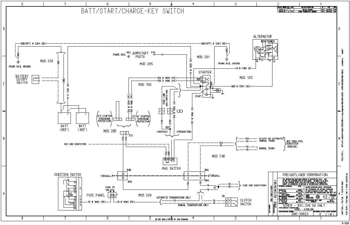
Diagram Sterling Acterra Wiring Diagram Full Version Hd Quality Wiring Diagram Diagramref Nordest4x4 It

Wiring Diagram Ac Sharp Inverter New Service Ac Kota Serang Baru Diagram Kelistrikan Ac Split Servisi Co Wiring Diagram Diagram Electrical Circuit Diagram

Diagram Diagram Of Ac Package Unit Wiring Full Version Hd Quality Unit Wiring Diagrammd Prolococusanese It

18 Ls1 Engine Wiring Diagram Engine Diagram Wiringg Net Wiring Diagram Sensor Wire
Diagram Kohler Magnum Ignition Wiring Diagram Full Version Hd Quality Wiring Diagram Imdiagram Giardinowow It


Diagram Shopsmith Mark V Wiring Diagram Full Version Hd Quality Wiring Diagram Diagramref Nordest4x4 It

Diagram Duromax 16 Hp Wiring Diagram Full Version Hd Quality Wiring Diagram Diagramman Prolococusanese It